DIY : Battery relocation + CP-e extension
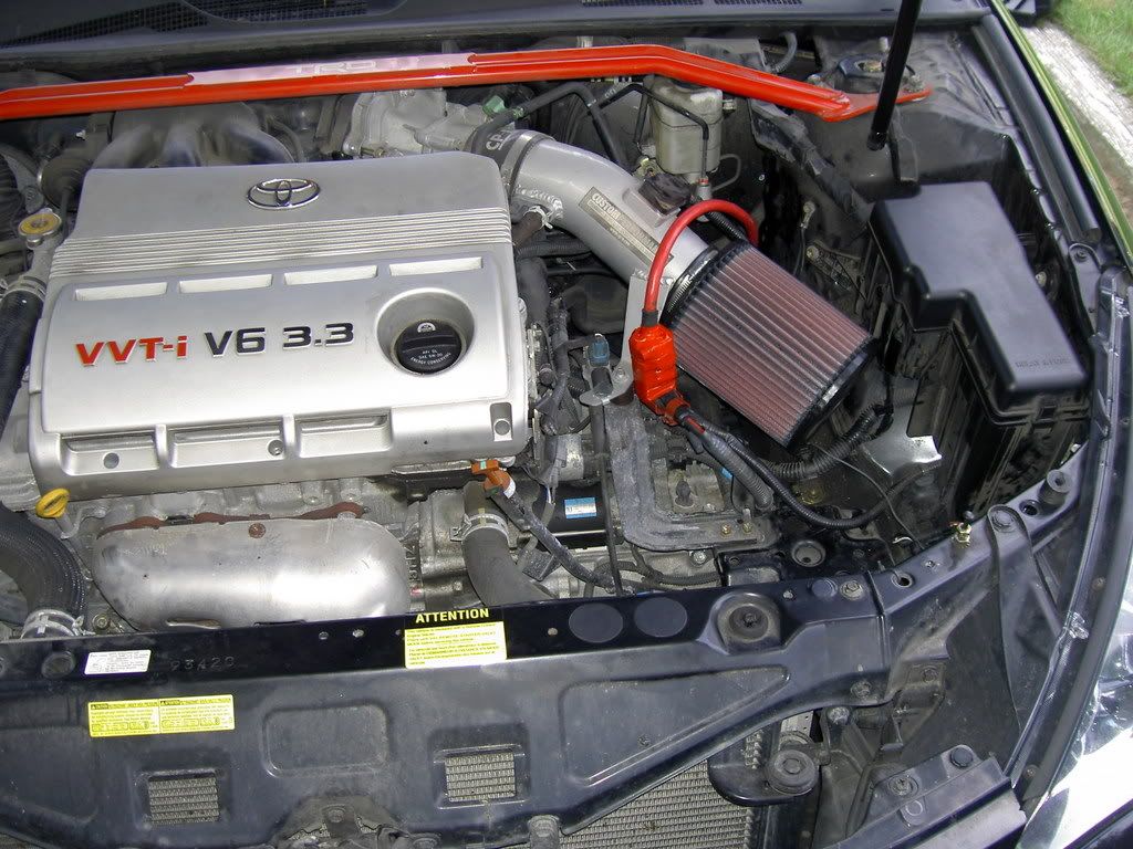
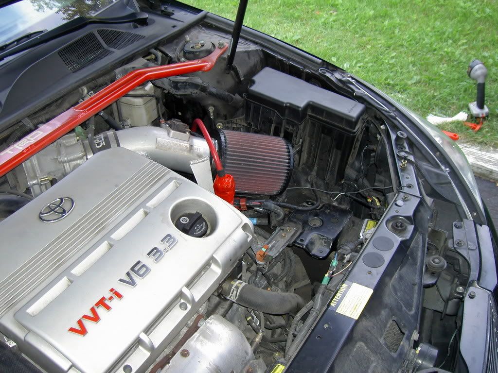
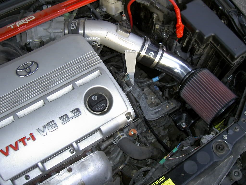
First, the main purpose of this mod is to free up the engine bay to let me (later on) put an extension to my CP-e pipe to get colder air.
Ok guys this is the tutorial section...do not post general question or opinion on here...I've already made an thread for it.
http://www.solaraguy.org/viewtopic.php?t=34577
Only specific question on the topic.
Also note that to play with electricity ask for a minimum security behavior and that I cannot be named responsible for any damage (car/person) doing this mod. Medium mod difficulty (nothing complicated as turbo setup) but ask for some drilling...
Thanks
===============================================
-------------------------
Purchase part
-------------------------
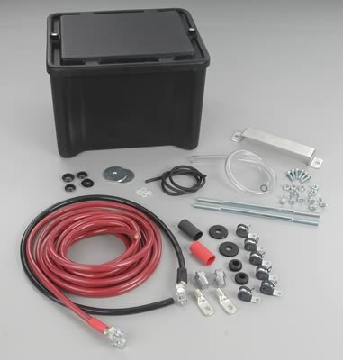
I bought the kit and the switch from Summitracing.com
The kit ($109.95)
SUM-G1231-K
http://store.summitracing.com/partdetail.asp?autofilter=1&part=SUM%2DG1231%2DK&N=700+400304+1005+115&autoview=sku
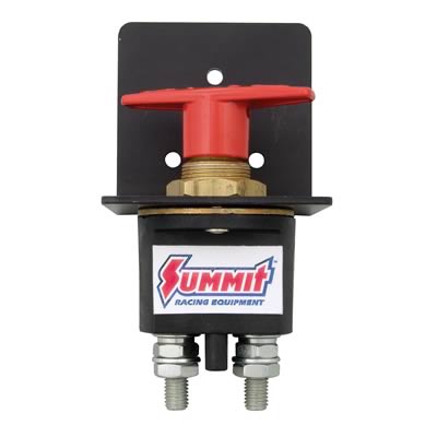
The switch ($49.95) (just must to have)
SUM-830050
http://store.summitracing.com/partdetail.asp?autofilter=1&part=SUM%2D830050&N=700+0&autoview=sku
The battery (paid 200$ (CAD) at Wal-Mart)
Optima redtop group 34/78
==============================================
-------------------------
The tools
-------------------------
12mm, 14mm, 17mm socket
9/16" socket (maybe forgot some...but most common thru the process)
Drill with
1/4" wood drill bit (for the swith on the box)
3/4" wood drill bit (for the box)
3/4" metal drill bit (for the firewall)
Tie-wrap
Saw for the board
Wire size vs length (http://www.rbeelectronics.com/wtable.htm )
==============================================
Steps
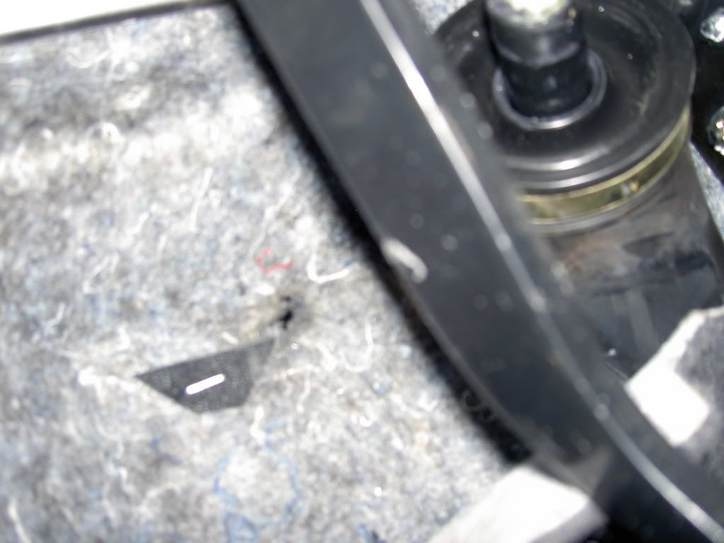
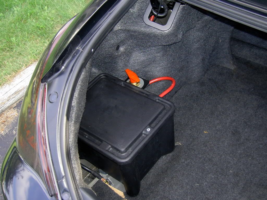
1. Locating the spot under the car where you could have access to bolt the rods passing thru the box. I choose left side because right side was block by the exhaust line. Took off the plastic rack. Place the box then place the battery where you want it to sit. I choose the middle of the isolating paste on the driver/passenger side axis and choose to put the left read corner of the lid in the curve of the tailights shaped carpet wall.
Under view (don't forget to put a lot of grease on those bolts and rods)
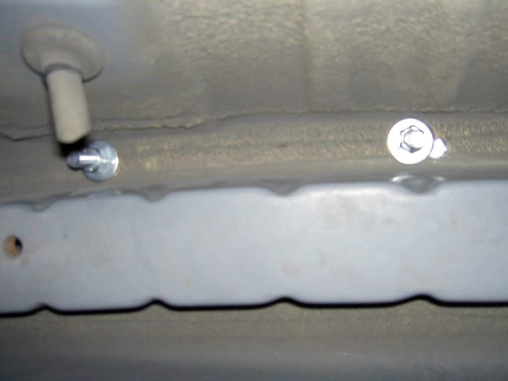
Don't use the down bracket as template for the 2 holes as the instruction says. The reason is because the box is trapezoid (top larger than bottom). You can see it on last pic (3rd hole...) I suggest you to use the down bracket as template for just one hole then place the box over it. The hole has to be at 1/4"-3/8" inner the box to let the usage of a washer (important to not tear the thick plastic during usage of the car). Put something heavy or better ask someone to keep the box in place. Go under the car and drill at least a spot in the box using the hole that you already made in the car with the down bracket as a template. For the second hole be sure to align your box correctly and from 1/4" to 3/8" drill and hole thru the box and the car. Again take your time on this part...I'm trying to explain it the best I can...but there is part you have to figure it out yourself.
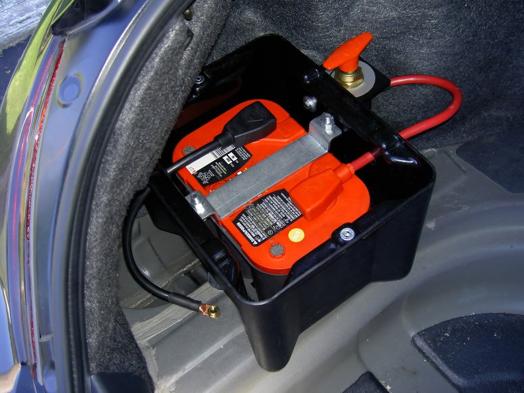
Hint : since the battery weight 40 pounds, it is a good idea to balance the weight on solid base. To do so, push the box further possible toward outside of the car (with carpet wall ON). Then you'll be able to place the battery. The key is the down backet location.
DON'T FORGET to put back board floor (need a little cut) and floor carpet just 2 holes for the rod to pass thru...I forget this step and it look less professional !
2. Put the battery in the box and (take it off) align yourself to drill the wire holes as instructions says
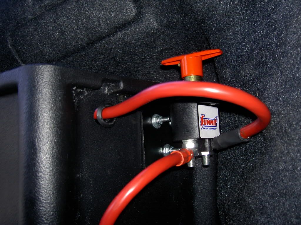
3. Use a board and put the kill switch back down in order to create a template. Color the 3 holes with black marker on the board. Use this homemade template and drill in those spots without moving the board to get a perfect job. Then you'll be able to screw the siwtch on the box. Use big washer with small one to help the box stand the weight of the switch. Put the screw facing the outside of the box...it will not create any interference.
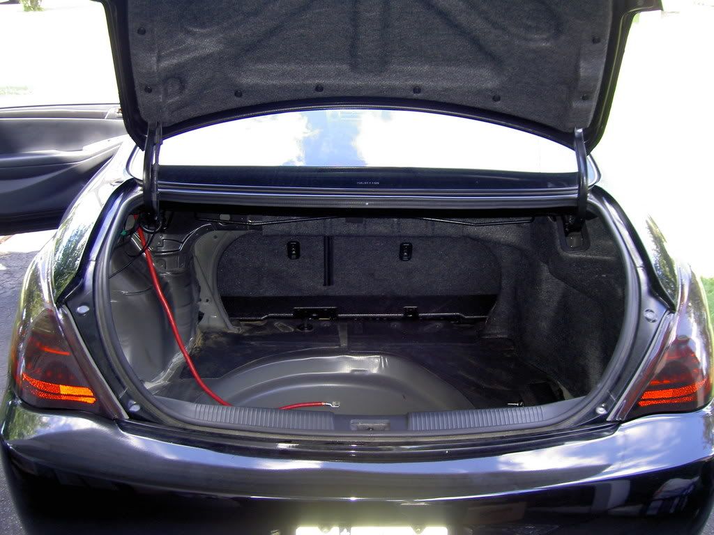
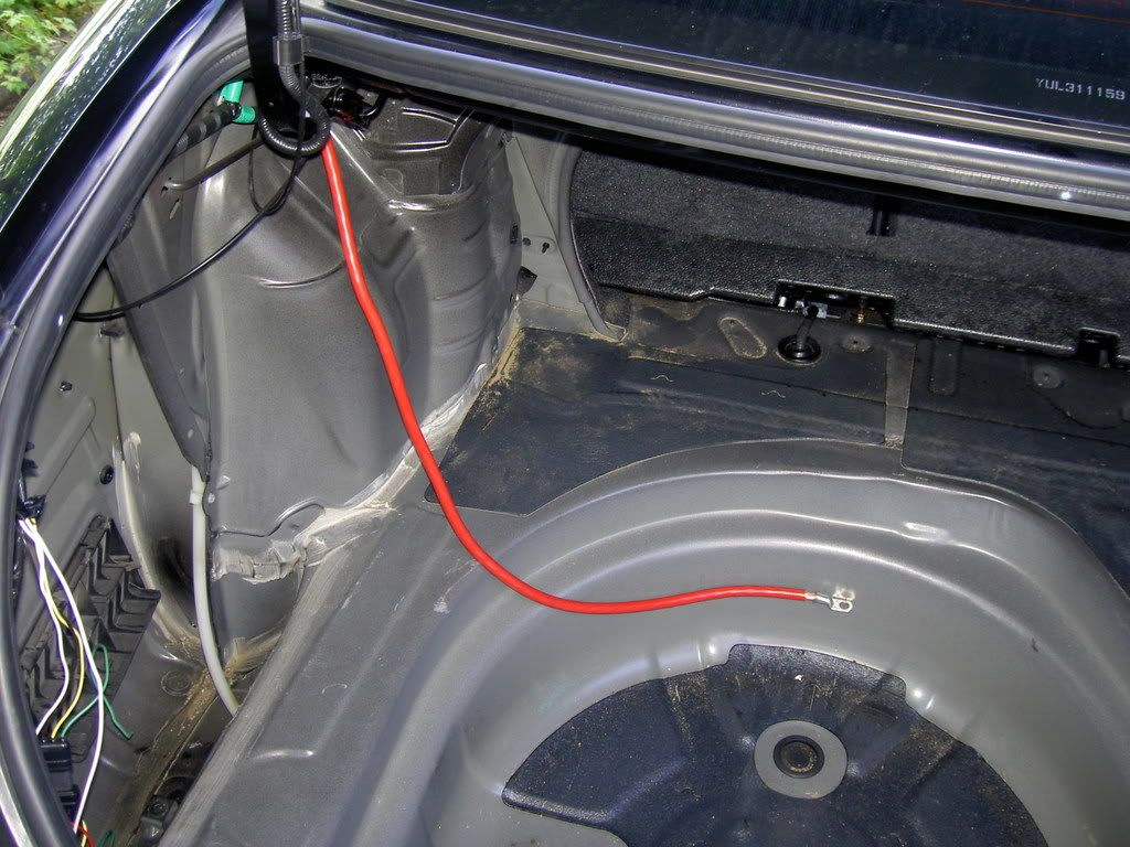
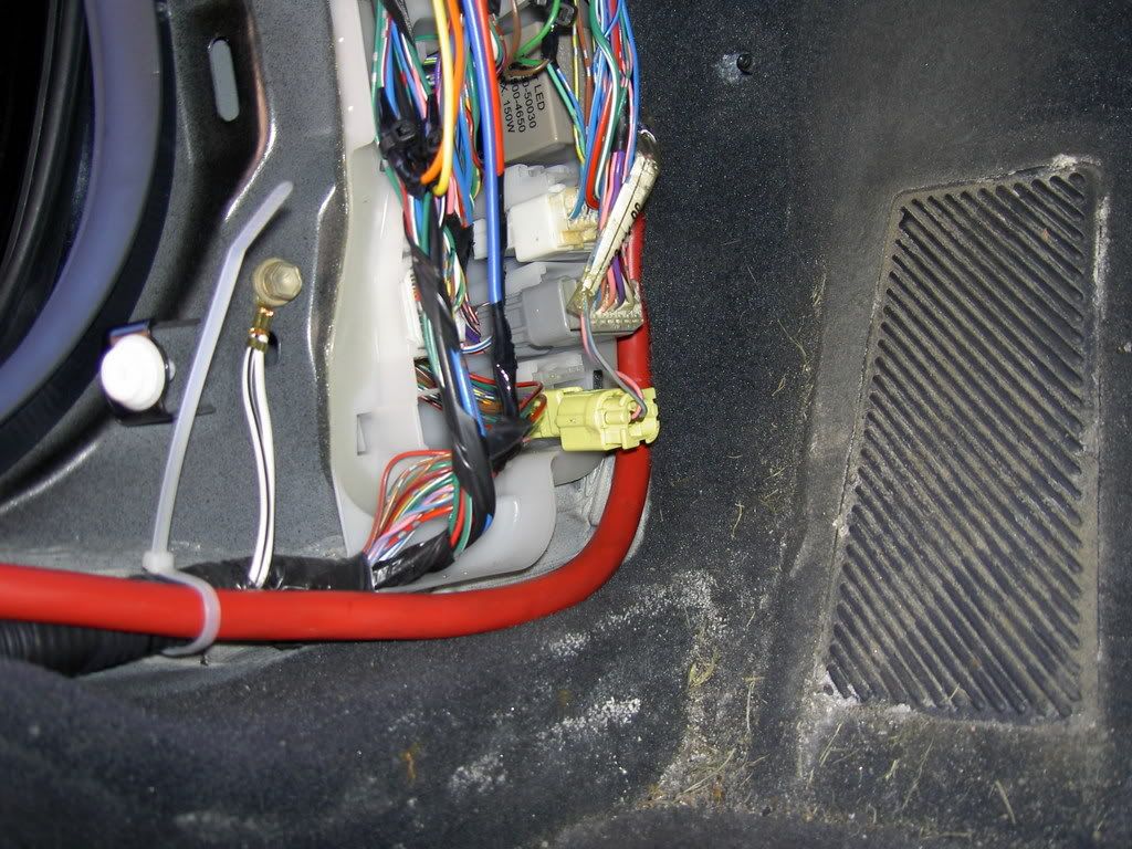
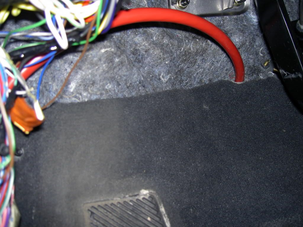
4. Now that your hole or done in the trunk/box section, you may want to pass the positive wire toward the engine bay. Here are so shot from the trunk.
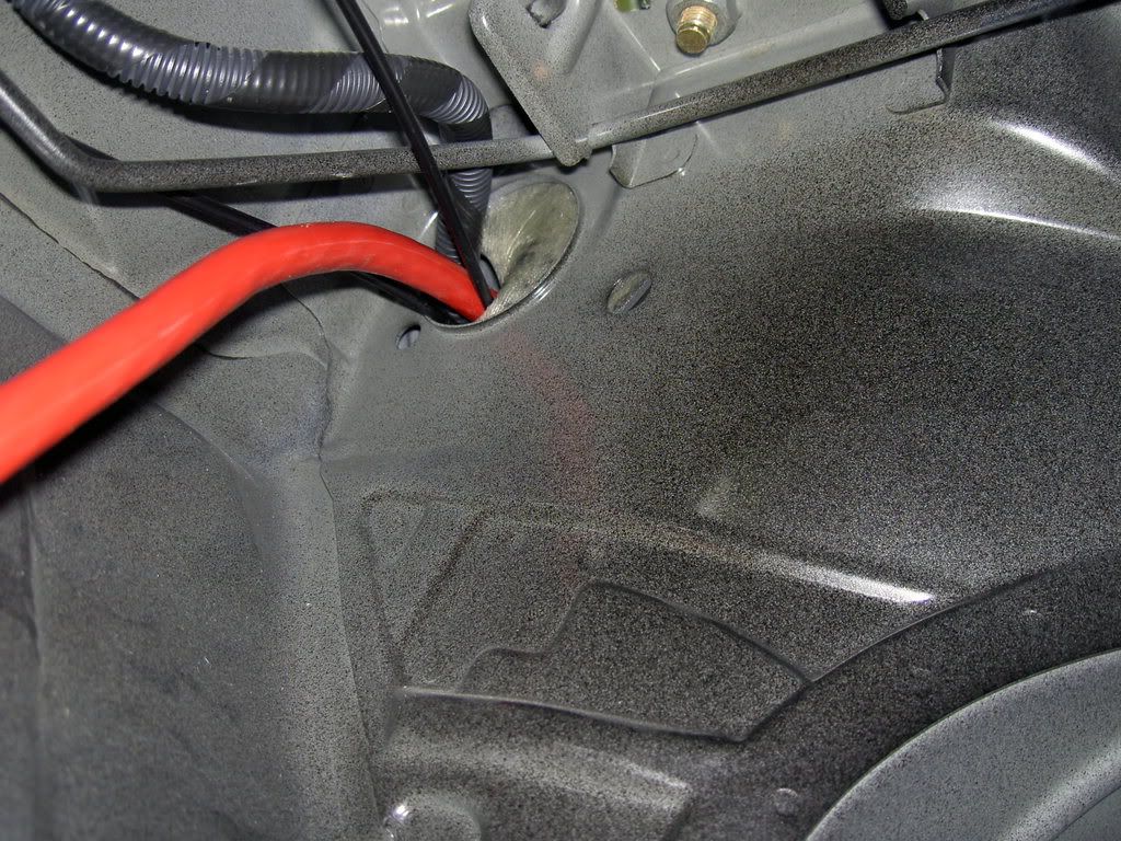
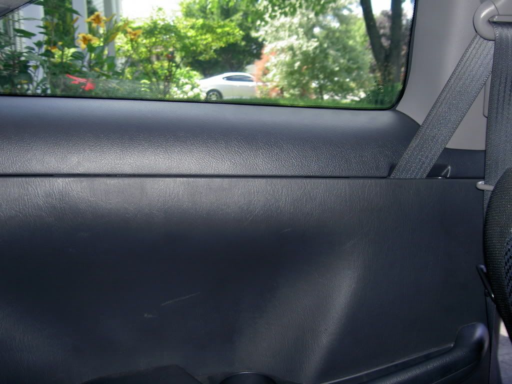
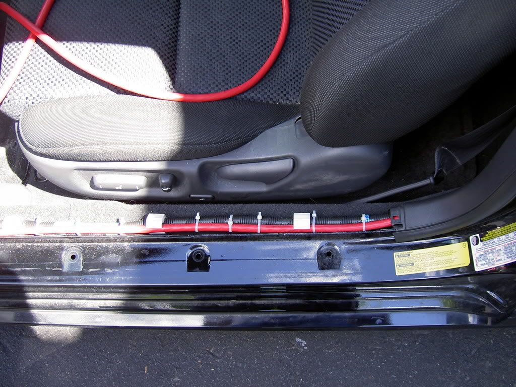
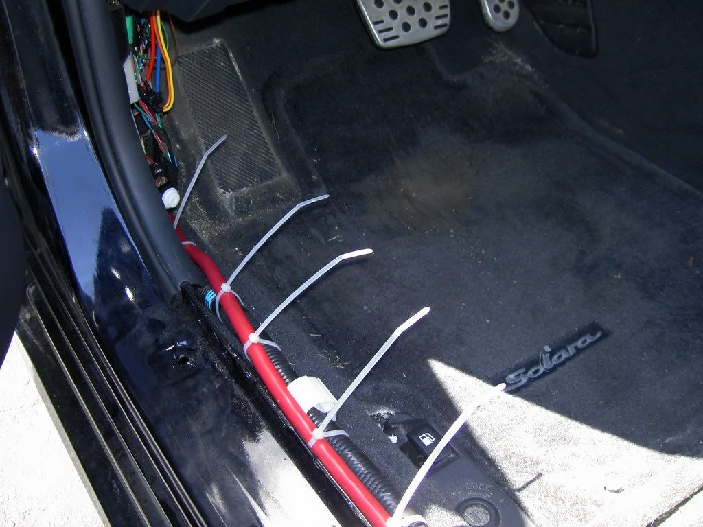
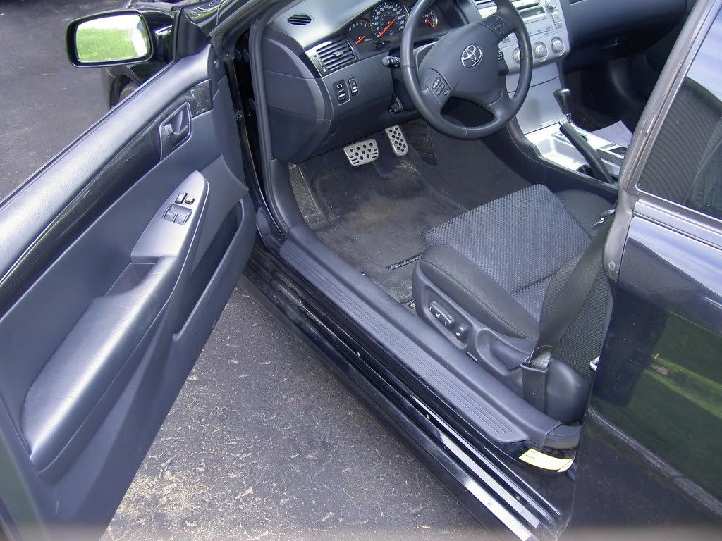
5. Continue inside the car on driver rear seat. Pull gently on the wall toward inside. I start with the part nearest to the door.
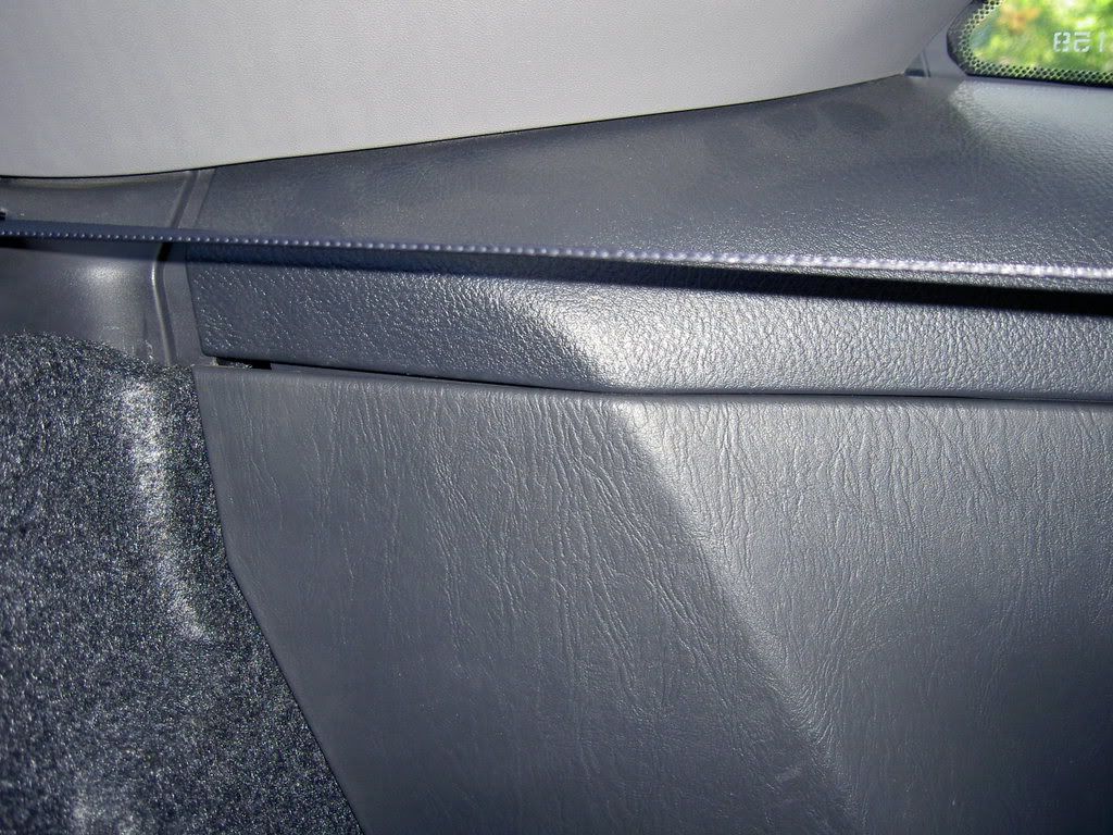
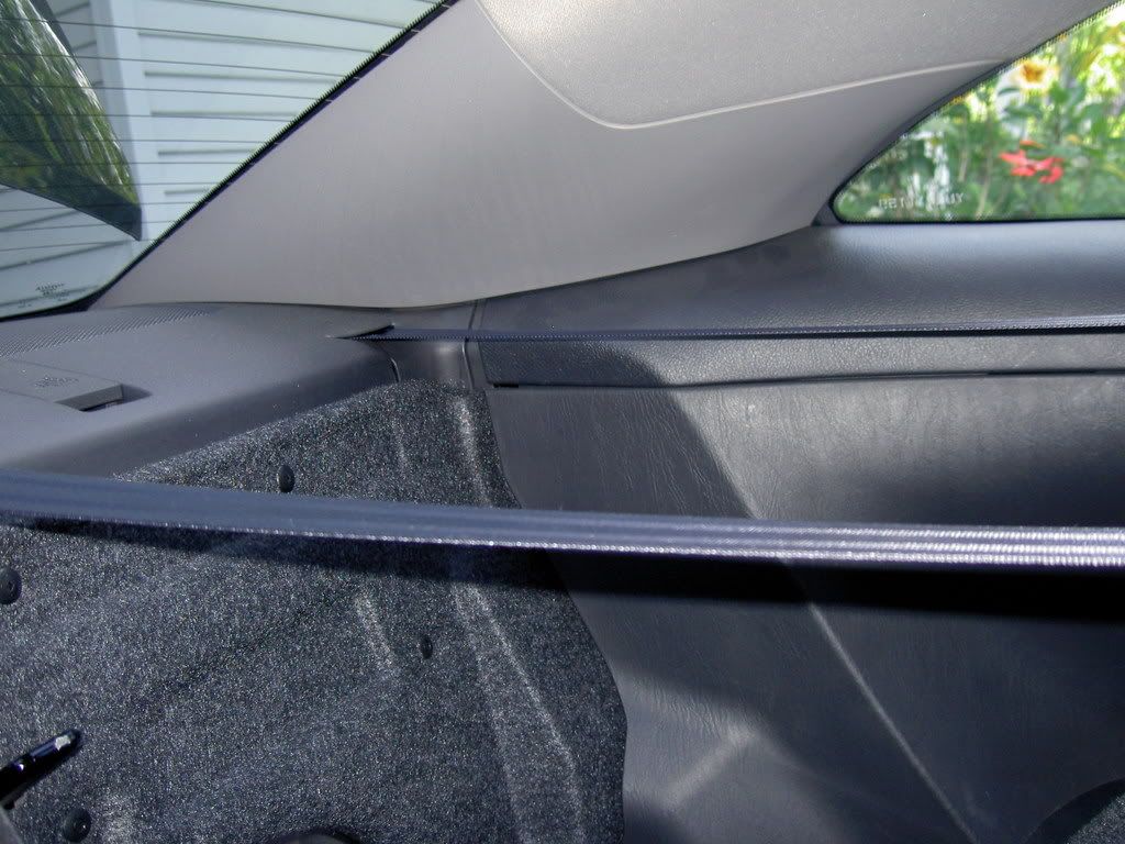
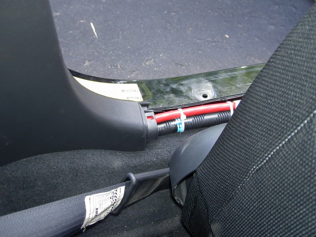
6. Make pass the wire thru the bottom as well...becareful to not move too mush isolating material. I pass down the seat belt "charger" to land at this point after taking off the door floor trim.
7. Now is time to drill an 3/4" hole thru the firewall. Look closely to the pic inside/outside to locate the same place on your car. If you think to have a better location to pass the wire good for you...
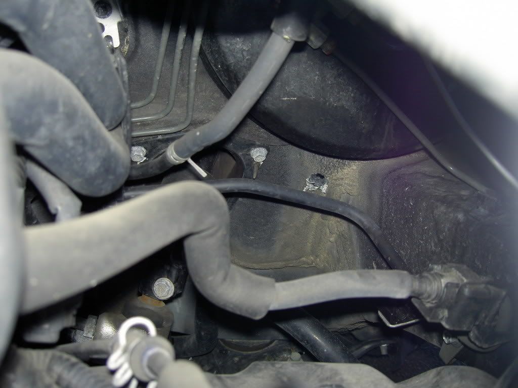
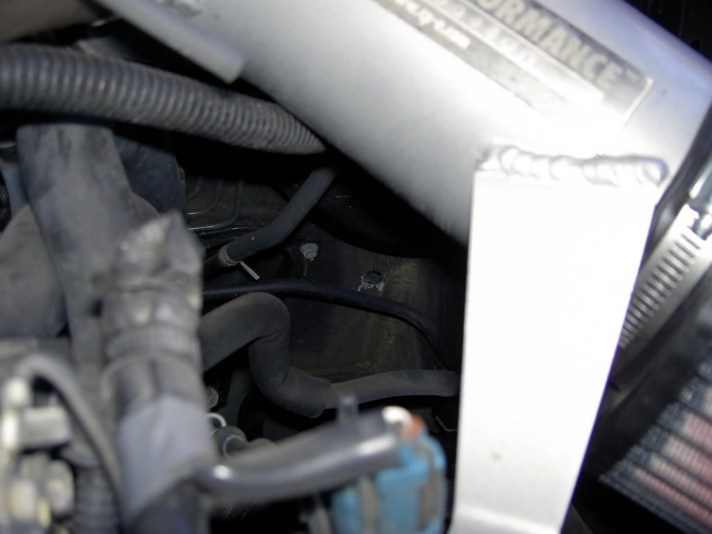
8. Then put the grommet. Pain in the ass...better to trim the excess of metal in the engine bay around the hole you just made.
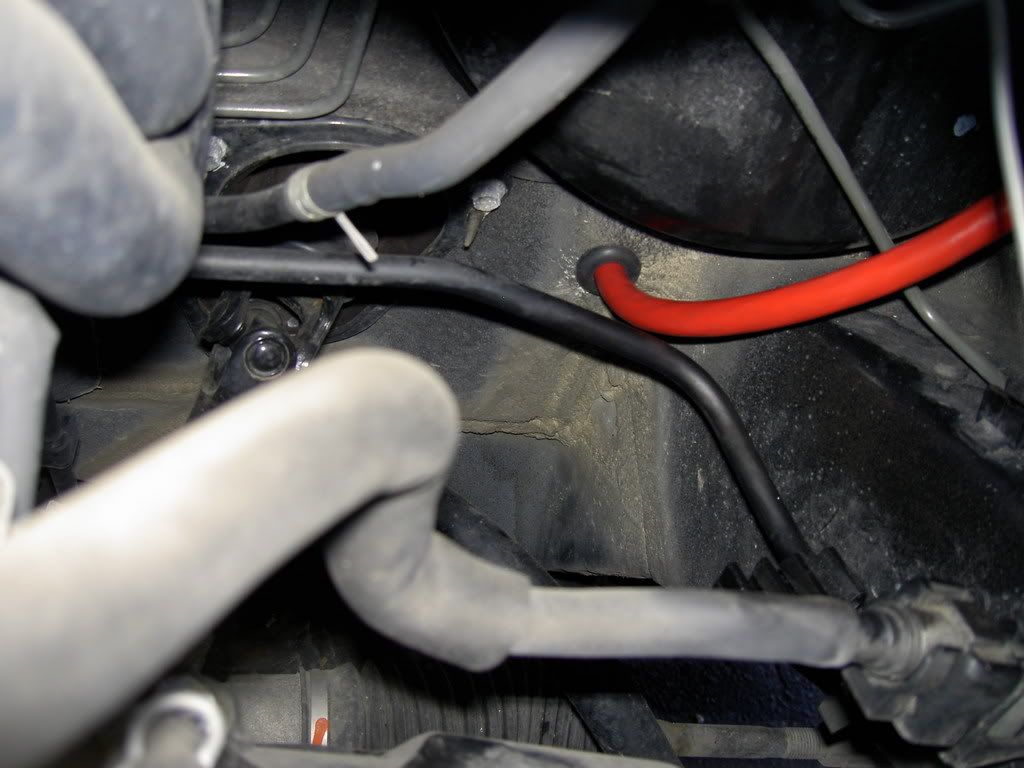
9. Once its done...it's a no contest. Just finish to route the wire.
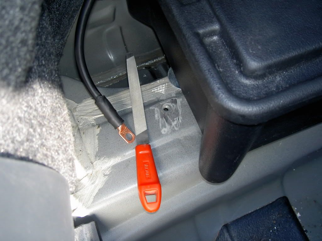
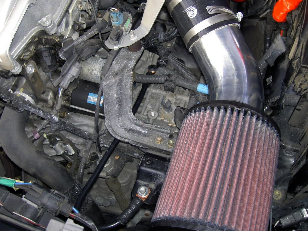
10. File down the paint around the hole for the negative. I use the hole from the plastic rack.
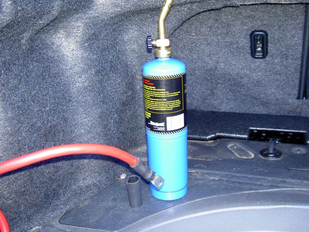
11. Do the connections.
I use this to complete my connection. I try also the heat gun...I think heat gun is better !!
FORBIDDEN !!!
Do not take off the stock ground...or just replace it like I did.
12. I took off the stock negative wire to make some space.
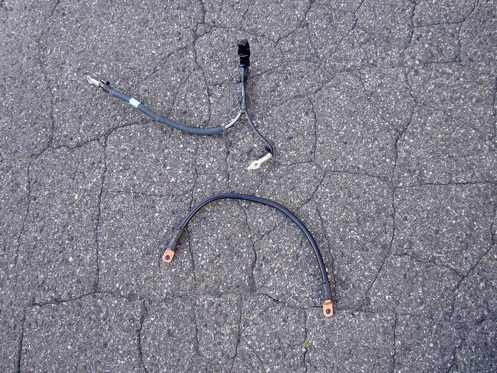
I replace the ground that way
13. Now it's time to make the final terminal connection. I used the bolt that is already on the terminal.
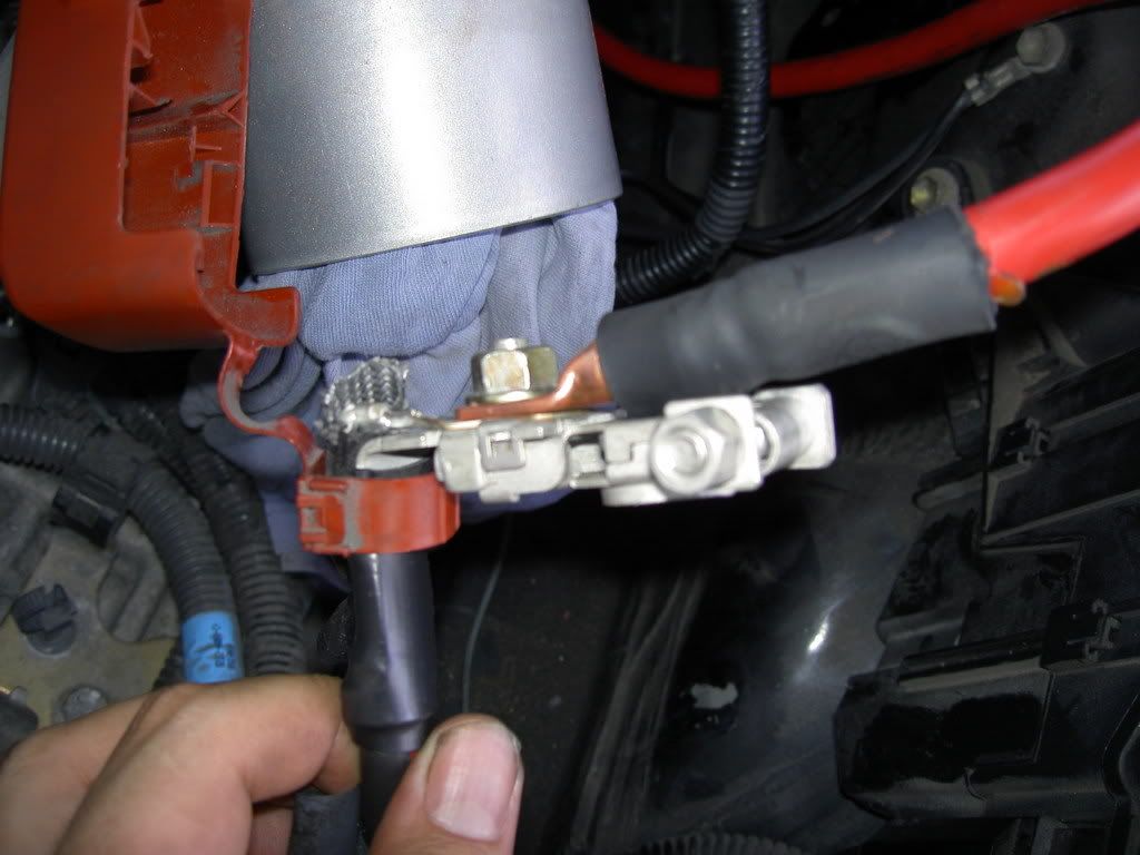
14. Isolating everything by using a electric red tape.
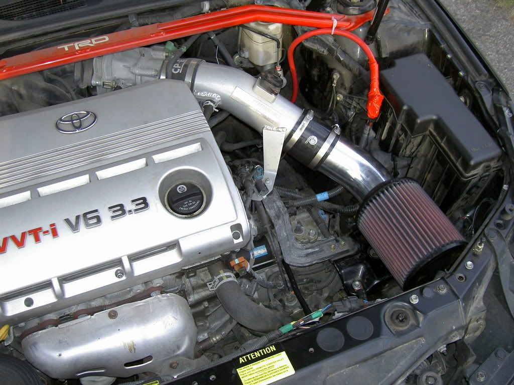
15. I choose to pass the wire this way but I think you can make it closer to the driver strut tower by cutting the stock dark gray tie-wrap.
Put everything back on
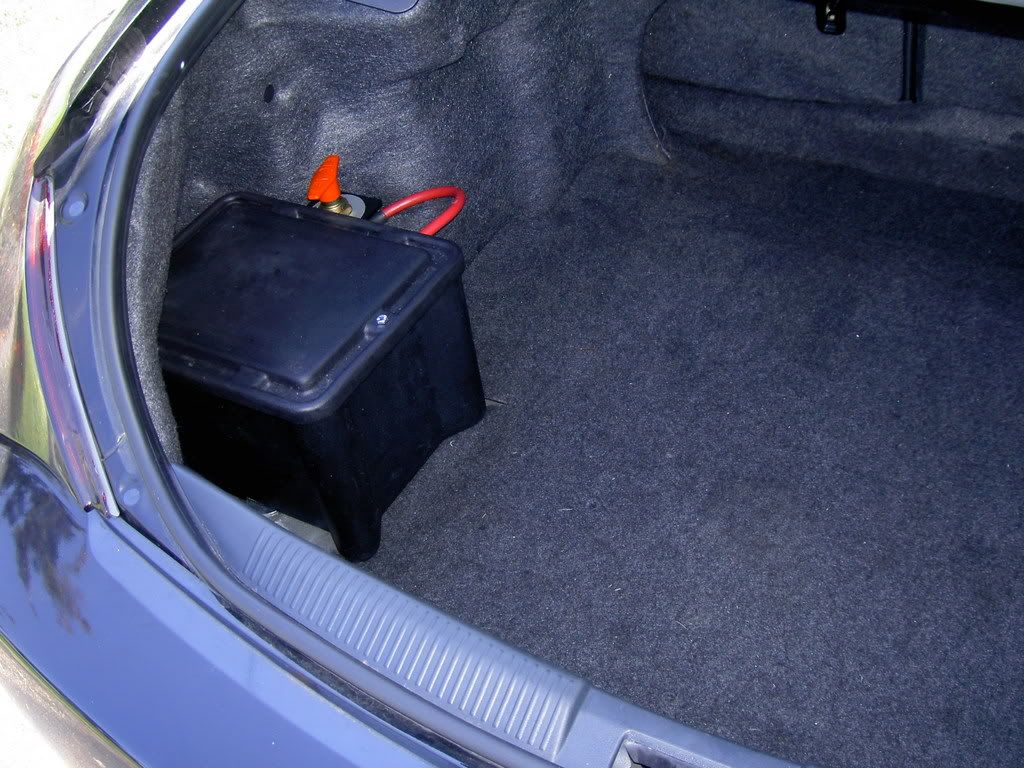
16. Push and lock the switch to ON !!!
Ok guys this is the tutorial section...do not post general question or opinion on here...I've already made an thread for it.
http://www.solaraguy.org/viewtopic.php?t=34577
Only specific question on the topic.
Also note that to play with electricity ask for a minimum security behavior and that I cannot be named responsible for any damage (car/person) doing this mod. Medium mod difficulty (nothing complicated as turbo setup) but ask for some drilling...
Thanks
===============================================
-------------------------
Purchase part
-------------------------
I bought the kit and the switch from Summitracing.com
The kit ($109.95)
SUM-G1231-K
http://store.summitracing.com/partdetail.asp?autofilter=1&part=SUM%2DG1231%2DK&N=700+400304+1005+115&autoview=sku
The switch ($49.95) (just must to have)
SUM-830050
http://store.summitracing.com/partdetail.asp?autofilter=1&part=SUM%2D830050&N=700+0&autoview=sku
The battery (paid 200$ (CAD) at Wal-Mart)
Optima redtop group 34/78
==============================================
-------------------------
The tools
-------------------------
12mm, 14mm, 17mm socket
9/16" socket (maybe forgot some...but most common thru the process)
Drill with
1/4" wood drill bit (for the swith on the box)
3/4" wood drill bit (for the box)
3/4" metal drill bit (for the firewall)
Tie-wrap
Saw for the board
Wire size vs length (http://www.rbeelectronics.com/wtable.htm )
==============================================
Steps
1. Locating the spot under the car where you could have access to bolt the rods passing thru the box. I choose left side because right side was block by the exhaust line. Took off the plastic rack. Place the box then place the battery where you want it to sit. I choose the middle of the isolating paste on the driver/passenger side axis and choose to put the left read corner of the lid in the curve of the tailights shaped carpet wall.
Under view (don't forget to put a lot of grease on those bolts and rods)
Don't use the down bracket as template for the 2 holes as the instruction says. The reason is because the box is trapezoid (top larger than bottom). You can see it on last pic (3rd hole...) I suggest you to use the down bracket as template for just one hole then place the box over it. The hole has to be at 1/4"-3/8" inner the box to let the usage of a washer (important to not tear the thick plastic during usage of the car). Put something heavy or better ask someone to keep the box in place. Go under the car and drill at least a spot in the box using the hole that you already made in the car with the down bracket as a template. For the second hole be sure to align your box correctly and from 1/4" to 3/8" drill and hole thru the box and the car. Again take your time on this part...I'm trying to explain it the best I can...but there is part you have to figure it out yourself.
Hint : since the battery weight 40 pounds, it is a good idea to balance the weight on solid base. To do so, push the box further possible toward outside of the car (with carpet wall ON). Then you'll be able to place the battery. The key is the down backet location.
DON'T FORGET to put back board floor (need a little cut) and floor carpet just 2 holes for the rod to pass thru...I forget this step and it look less professional !
2. Put the battery in the box and (take it off) align yourself to drill the wire holes as instructions says
3. Use a board and put the kill switch back down in order to create a template. Color the 3 holes with black marker on the board. Use this homemade template and drill in those spots without moving the board to get a perfect job. Then you'll be able to screw the siwtch on the box. Use big washer with small one to help the box stand the weight of the switch. Put the screw facing the outside of the box...it will not create any interference.
4. Now that your hole or done in the trunk/box section, you may want to pass the positive wire toward the engine bay. Here are so shot from the trunk.
5. Continue inside the car on driver rear seat. Pull gently on the wall toward inside. I start with the part nearest to the door.
6. Make pass the wire thru the bottom as well...becareful to not move too mush isolating material. I pass down the seat belt "charger" to land at this point after taking off the door floor trim.
7. Now is time to drill an 3/4" hole thru the firewall. Look closely to the pic inside/outside to locate the same place on your car. If you think to have a better location to pass the wire good for you...
8. Then put the grommet. Pain in the ass...better to trim the excess of metal in the engine bay around the hole you just made.
9. Once its done...it's a no contest. Just finish to route the wire.
10. File down the paint around the hole for the negative. I use the hole from the plastic rack.
11. Do the connections.
I use this to complete my connection. I try also the heat gun...I think heat gun is better !!
FORBIDDEN !!!
Do not take off the stock ground...or just replace it like I did.
12. I took off the stock negative wire to make some space.
I replace the ground that way
13. Now it's time to make the final terminal connection. I used the bolt that is already on the terminal.
14. Isolating everything by using a electric red tape.
15. I choose to pass the wire this way but I think you can make it closer to the driver strut tower by cutting the stock dark gray tie-wrap.
Put everything back on
16. Push and lock the switch to ON !!!
 This should help many who my attempt to relocate their battery.